Design & Engineering
Design & Engineering
Design Depth & Expertise
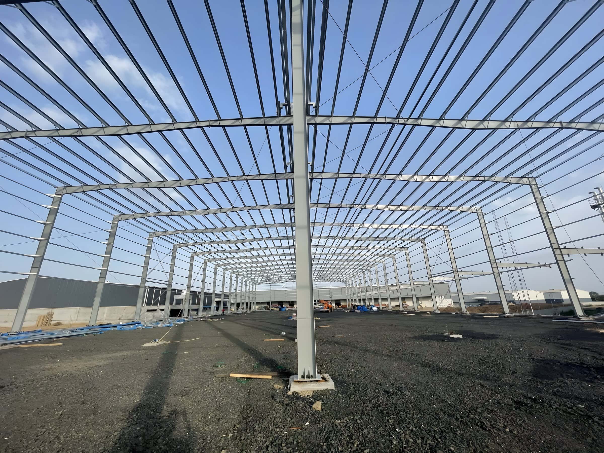
The main framing of PEB systems is analysed by the stiffness matrix method. The design is based on allowable stress design (ASD) as per the American Institute of Steel Construction (AISC) specification or IS 800. The design program provides an economical and efficient design of the main frames and lets the user run it in different modes to produce the frame geometry, loading and desired load combinations specified by the chosen building code.
The program runs through the specified maximum number of design cycles to arrive at an acceptable design, using the stiffness matrix method to solve for displacements and forces. The strain energy method is used to calculate the fixed-end moments, stiffness and carry-over factors, with numerical integration.
Design Codes
Design Codes
The main design codes generally used are:
- AISC: American Institute of Steel Construction Manual
- AISI: American Iron and Steel Institute Specifications
- MBMA: Metal Building Manufacturers Association Code
- ANSI: American National Standards Institute Specifications
- ASCE: American Society of Civil Engineers
- UBC: Uniform Building Code
- IS: Indian Standards
Design Criteria
Design Criteria
The main design criteria generally used are:
- Design method: Allowable stress design method as per the AISC specifications.
- Deflections: Unless otherwise specified, deflections follow MBMA and AISC criteria and standard industry practice.
- Primary framing: Moment-resisting frames with pinned or fixed bases.
- Secondary framing: Cold-formed Z or C sections for purlins and girts, designed as continuous beams spanning over rafters and columns with laps.
- Longitudinal stability: Wind load on the building end walls is transferred through the roof purlins to braced bays and carried to the foundations through diagonal bracing.
- Design software: The latest software used for design includes AutoCAD, Tekla, Pro/E and SolidWorks.
- Design process: Frame data is assembled from the number of frame members, joints and degrees of freedom, the restraint conditions and the elastic properties of the members, and member section properties are computed. The overall joint stiffness matrix is built by summing the individual stiffness matrices for all possible displacements. The load vector is generated from the loading data, and the unknown displacements are found by inverting the overall joint stiffness matrix and multiplying it by the load vector.